



Your shopping cart is currently empty.
Electric Brakes on a Custom Dexter Axle: Sizes, Brake Flange, Pre-Wire and Setup
Adding electric brakes to a custom built Dexter axle comes down to a few choices: the right brake size for the axle capacity, a brake flange to mount it on, how the brake wire gets to the brakes, and whether each axle gets brake hubs or idler hubs. This guide walks through each one, then covers magnets, adjustment, burnishing, the brake controller and wiring.
Follow the instructions for the axle and brake assemblies fitted to your trailer. Where a Dexter bulletin and Dexter's catalog or manual disagree, the bulletin is the newer instruction. The burnishing section below uses Lippert's Electric Drum Brake Break-In Period sheet, TI-086. If your brake manufacturer specifies a different procedure, follow its instructions.
Key takeaway
- Match the brake to the axle capacity: Brake size and capacity must match the axle application.
- Brake flange: Custom beams of 3,500 lb. and up always come with a brake flange. Only the 2,000 lb. forms make it a choice.
- Pre-wire: Choosing pre-wire gets Dexter's inner wiring, with the brake wire run inside the axle tube.
- Brakes on every axle: Dexter recommends brakes on every axle, but check with your local DOT.
- Burnish, then set the controller: New electric brakes need a break-in before you fine-tune the brake controller.
Terms used in this guide
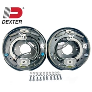
- Brake flange: The flange welded to the axle behind the spindle. The brake assembly bolts to it.
- Pre-wire: The order form option for having the electric brake wire run through the axle tube. Dexter calls this inner wiring.
- Idler hub: A hub with no brake.
- Brake hub: A hub and drum that works with a brake assembly.
- Magnet: The electromagnet inside an electric brake. Current from the brake controller energizes it to apply the brake.
- Brake controller: The unit in the tow vehicle that sends power to the trailer brake magnets.
How electric trailer brakes work
Dexter's service manual compares electric trailer brakes to the drum brakes on a car. The difference is that car brakes are applied by hydraulic pressure, while electric trailer brakes are applied by an electromagnet. When the controller sends current to the brake, the magnet is attracted to the turning armature surface of the drum. That moves the actuating lever, which pushes the primary shoe out against the drum, and the adjuster then moves the secondary shoe into contact. More current makes the magnet grip harder, increasing braking force.
The manual lists these advantages of electric brakes:
- They can be adjusted at the controller for different road and load conditions.
- They can be modulated for more or less braking force, easing the load on the tow vehicle brakes.
- They have very little lag between the tow vehicle brakes and the trailer brakes.
- In an emergency, they can provide some braking independent of the tow vehicle.
Electric brake sizes by axle capacity
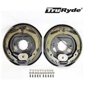
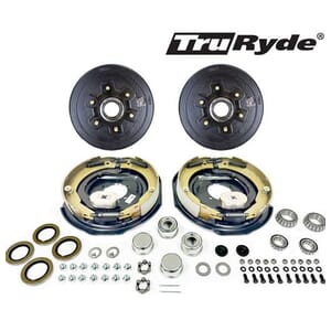
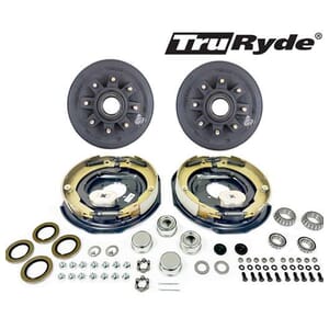
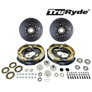
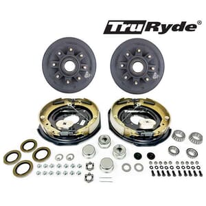
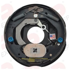
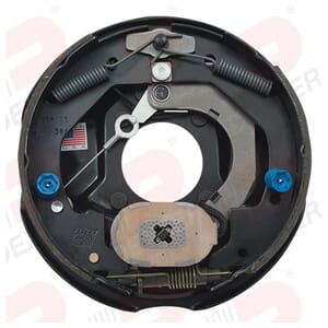
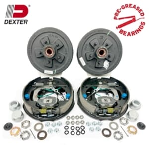
Southwest Wheel sells both complete electric brake kits and brake assembly pairs. Each complete kit includes hubs and drums plus backing plates for one axle. Brake assembly pairs are the left and right brakes only; hubs and drums are separate. Match the listing to what you need.
| Axle capacity | Electric brake size | Example kits and brakes |
|---|---|---|
| 2,000 lb. | 7" x 1-1/4" (2,200 lb. brake) | Needs the brake flange option on the custom 2,000 lb. beam. See Build a Complete Dexter Trailer Axle. |
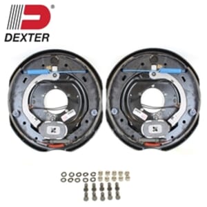
| 3,500 lb. | 10" x 2-1/4" (3,500 lb.) | TruRyde standard BK545ELE-IPS; TruRyde self-adjusting BK545ELEAUTO-IPS; Dexter pre-greased Nev-R-Adjust PGBK545ELEAUTO |
| 4,400 lb. | 10" x 2-1/4" (4,400 lb.), manual or Nev-R-Adjust | Dexter Nev-R-Adjust K23-478-00 (left) and K23-479-00 (right) |
| 5,200 lb. | 12" x 2", the same brake as 7,000 lb. | Southwest Wheel uses the 7,000 lb. backing plates with six-lug HD drums on 5,200 lb. axles. Standard BK13ELE-IPS; self-adjusting BK13ELEAUTO-IPS |
| 6,000 lb. | 12" x 2" | TruRyde standard 23134-IPS; TruRyde self-adjusting 23134AUTO-IPS; Dexter standard 23134-DB; Dexter Nev-R-Adjust 23134AUTO-DB. These are brake assemblies; hubs and drums are separate. |
| 7,000 lb. | 12" x 2" (7,000 lb.) | Standard BK42865ELE-IPS; self-adjusting BK42865ELEAUTO-IPS |
| 7,200 lb. | 12-1/4" x 2-1/2" (7,200 lb.), forward self-adjusting only | Select the brakes in the options of the 7,200 lb. custom beam: straight or 4" drop. |
| 8,000 lb. | 12-1/4" x 3-3/8" (8,000 lb.) | Brakes and hub and drums are sold separately. See the 8,000 lb. Standard Spring Dexter Trailer Axle Beam. |
Two Dexter bulletins affect this table:
- Dexter Product Bulletin 349 says the 10" x 2-1/4" 4,400 lb. brake is not interchangeable with the 10" x 2-1/4" 3,500 lb. brake. The same diameter and width does not mean the same brake.
- Dexter Product Bulletin 450 says Dexter offers only forward self-adjusting electric brakes on 7,200 lb. axles. Forward self-adjusting and manual brake assemblies should not be mixed by axle or by trailer. If replacing manual brakes with self-adjusting brakes, all brake assemblies on the trailer need to be replaced.
Not sure which capacity you need? See Choosing Trailer Axle Capacity: Hitch Weight, GAWR, Wheels and Tires.
Brake flange
The brake flange is where the brake assembly bolts to the axle. Without one, the axle can only run idler hubs.
- 3,500 lb. and up: Every custom beam comes with a brake flange, so there is no flange choice on those forms.
- 2,000 lb.: The straight and 4" drop custom forms offer the brake flange as an option. Add it if the axle will have brakes now or may have them later.
For the full list of beam options, see Dexter Axle Options: Tube, E-Z Lube, Pre-Wire and Brake Flange.
Pre-wire (Dexter inner wiring)
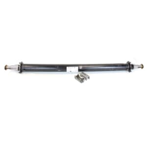
Every custom form asks whether you want the axle pre-wired. When you choose pre-wire, Dexter runs the electric brake wire through the axle tube. Dexter's catalog calls this an inner wiring system for easier installation and protection of brake wiring.
Pre-wire is for electric brakes. Choose it when the axle has, or will have, electric brakes. On a 2,000 lb. beam, electric brakes also need the brake flange.
The wiring also helps you install the axle facing the right way. Dexter's catalog says electric brake wires exit the brake backing plates toward the rear of the axle, and on leaf spring axles with inner wiring the wires exit the tube toward the rear of the axle. The front of the axle must face the front of the trailer.
Brake hubs or idler hubs
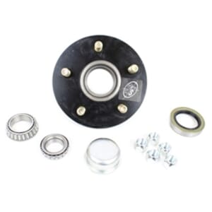
Every axle needs two hubs, one for each spindle. A complete electric brake kit includes two hub and drums along with the left and right brakes, so do not order idler hubs for an axle that gets a complete brake kit. Brake assembly pairs do not include hubs and drums.
An axle without brakes takes two idler hubs, for example the 545LB1E hub for a 3,500 lb. axle.
Dexter recommends brakes on every axle, but check with your local DOT. Dexter's applications guide adds that trailer brakes help the tow vehicle brakes last longer and make for safer operation, and that commercial trailers must meet Federal Motor Carrier Safety Regulations, which call for brakes on each wheel for most applications.
Ordering the rest of the axle? See Build a Complete Dexter Trailer Axle.
Burnishing new electric brakes
New electric drum brakes need a break-in before they reach full performance. Lippert's Electric Drum Brake Break-In Period sheet (TI-086 / CCD-0001947, Rev. 12.05.2025) applies to new axles and whenever new brake shoes and/or magnets are installed. Burnishing seats both the shoe lining material and the electromagnets. During break-in, the linings wear faster than after they are seated.
The following is Lippert's published procedure. If the manufacturer of your brake assemblies specifies different steps, follow its instructions.
Lippert specifies 20 to 50 brake applications, starting at 40 mph and slowing to 20 or 25 mph with approximately 8 to 10 volts applied to the trailer brakes. Perform all burnishing at posted speeds and only where conditions allow the procedure safely.
Before starting: Check the hitch connection, electrical connections and sway bars, and connect the breakaway cable.
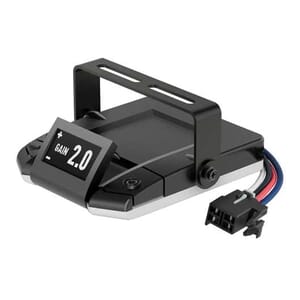
- Turn the GAIN on the trailer brake control to the maximum level.
- Bring the tow vehicle and trailer to 40 mph, observing posted speeds.
- Move the slide mechanism on the brake controller to apply 8 to 10 volts to the trailer brakes, allowing the combination to slow to 20 or 25 mph. Lippert says not to use the tow vehicle brakes or exhaust brakes during these burnishing applications, so the trailer brakes seat by slowing both the tow vehicle and trailer.
- Release the slide mechanism on the brake controller.
- Continue down the road, repeating the applications at one-mile intervals. Lippert says a noticeable difference in brake performance may occur in as few as 10 applications.
- Evaluate brake performance after 20 to 50 applications. When the brakes feel well seated, pull over at the next exit or another safe location to check the results.
- The brake and axle area may show smoke from the procedure, and the area around the brakes should be hot.
- Do not touch the brake drum directly. Lippert instructs hovering a hand around the area, not touching it. If available, use a temperature gun; the sheet specifies a target of 350 to 400 degrees.
- Lippert directs repeating the procedure if there is no smoke or the proper heat has not been reached. Do not touch the drum to test it. A drum that remains cold may indicate improper brake adjustment or a wiring concern.
After 50 applications, Lippert says the brake lining material will be fully cured from the heat and develop close to 100 percent contact with the brake drum surface. Complete break-in before fine-tuning the controller for normal driving.
Setting the brake controller
Set up the controller according to its manufacturer's instructions. Dexter's manual adds these points:
- The controller should send about 2 volts to the brakes when the pedal is first pressed, then gradually increase to 12 volts as pedal pressure increases. A controller that jumps straight to high voltage, even on a gradual stop, can cause harsh braking and wheel lockup.
- Most controllers modulate current with brake pedal pressure or the tow vehicle's deceleration. Electronic or timing controllers do not provide proportional modulation, and Dexter says they are not the best choice for optimum braking.
- Synchronization can only be set by road testing. Make several hard stops from 20 mph on a dry paved road free of sand and gravel, with no traffic around. If the trailer brakes lock and slide, lower the gain. If they do not, raise it slightly. Adjust just to the point of impending lockup.
- Dexter recommends the trailer brakes come on just slightly ahead of the tow vehicle brakes. When set correctly, the trailer will not jerk or push the tow vehicle.
- During normal driving, use the tow vehicle and trailer brakes together to stop the combined load. The trailer-brake-only applications above are specific to Lippert's burnishing procedure.
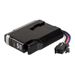
Proportional controllers include the CURT TriFlex NEXT (51146) and Assure (51160). Some vehicles also need a vehicle-specific controller harness, so have your year, make and model ready.
Wiring
Dexter's manual gives the minimum copper hookup wire size by the number of brakes and the distance from the hitch to the axle:
| Number of brakes | Hitch-to-axle distance | Minimum wire size (copper) |
|---|---|---|
| 2 | Any | 12 AWG |
| 4 | Under 30 ft. | 12 AWG |
| 4 | 30 to 50 ft. | 10 AWG |
| 6 | Under 30 ft. | 10 AWG |
| 6 | 30 to 50 ft. | 8 AWG |
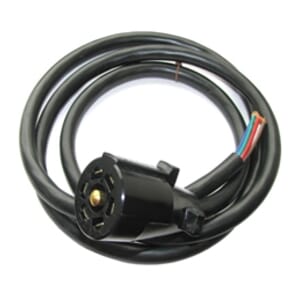
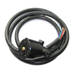
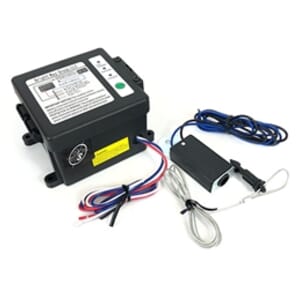
For a 12 gauge run, see the CURT 2-wire jacketed trailer brake cable (57038). With a TruRyde, Dexter or Lippert brake kit, Southwest Wheel recommends the 2382 breakaway kit and a 7-way connector, either the 6 ft. A7W6FTB or the 8 ft. A7W8FTB.
The manual says the most common electrical problem is low or no voltage and amperage at the brakes. Common causes are poor connections, open circuits, undersized wire, broken wires, blown fuses and a controller or resistor that is not working properly. Dexter does not recommend fusing the brakes.
Magnet current draw
You can check each magnet with an ammeter in the line at that magnet. Dexter's chart:
| Brake size | Amps per magnet | Two brakes | Four brakes | Six brakes | Magnet ohms |
|---|---|---|---|---|---|
| 7" x 1-1/4" | 2.5 | 5.0 | 10.0 | 15.0 | 3.9 |
| 10" x 1-1/2", 10" x 2-1/4", 12" x 2", 12-1/4" x 2-1/2", 12-1/4" x 3-3/8" | 3.0 | 6.0 | 12.0 | 18.0 | 3.2 |
If the system has a resistor, set it to zero or bypass it to get the maximum reading.
Brake adjustment
Dexter electric brakes with the self-adjusting feature need no manual adjustment. Dexter's forward self-adjust feature adjusts on both forward and reverse stops when lining wear opens enough gap. It is not available on all sizes.
Manual adjust brakes should be adjusted after the first 200 miles, when the shoes and drums have seated, then at 3,000 mile intervals or as use requires:
- Jack up the trailer and support it on jack stands rated for the load. Do not lift or support the trailer on any part of the axle or suspension.
- Remove the adjusting hole cover, if present, from the slot at the bottom of the backing plate.
- Turn the star wheel to expand the shoes until the wheel is very difficult to turn.
- Turn the star wheel back until the wheel turns freely with a slight lining drag.
- Replace the cover and lower the wheel.
- Repeat on every brake. For best results, set all brakes to the same clearance.
Magnets and shoes
- Check magnets with a straightedge. The magnet should be flat. Replace a magnet that is worn unevenly or abnormally.
- Replace the magnet if any part of the coil shows through the friction material, even if the wear is otherwise normal. Dexter also recommends refacing the drum armature surface when replacing magnets.
- Replace magnets in pairs, both sides of an axle. Dexter Product Bulletins 341, 387 and 388 repeat this rule.
- Replace linings worn to 1/16" or less, and shoes contaminated with grease or oil or abnormally scored or gouged. Replace both shoes on each brake and both brakes on the axle. Hairline heat cracks in bonded linings are normal.
- Do not get grease or oil on the linings, drums or magnets.
Frequently asked questions
Do I need a brake flange on a custom Dexter axle?
On 3,500 lb. and up, it is already included. On a 2,000 lb. custom beam, choose the brake flange option if the axle will ever have brakes.
What does pre-wire mean?
Dexter runs the electric brake wire through the axle tube. Dexter calls this inner wiring.
Do I order idler hubs with a brake kit?
No. A complete electric brake kit includes its own hubs and drums. Brake assembly pairs do not include hubs and drums. Idler hubs are for an axle without brakes.
Can I mix self-adjusting and manual electric brakes?
No. Per Dexter Product Bulletin 450, forward self-adjusting and manual brake assemblies should not be mixed by axle or by trailer.
How do I break in new electric brakes?
Lippert's TI-086 procedure calls for 20 to 50 applications using the controller slide to apply about 8 to 10 volts, slowing from 40 mph to 20 or 25 mph at one-mile intervals without tow vehicle or exhaust brakes. It also requires connection checks before starting and a heat check afterward. Follow the full burnishing section above, observe posted speeds and never touch a hot brake drum. Follow your brake manufacturer's instructions if they differ.
How often do I adjust electric brakes?
Manual adjust brakes: after the first 200 miles, then every 3,000 miles or as use requires. Self-adjusting Dexter brakes need no manual adjustment. Bearing service is a separate job; see Trailer Hub Bearing Adjustment and Grease, Step by Step.
New to these terms? See Trailer Axle Terms: A Plain-English Glossary.
Ready to build your axle?
Shop Custom Built Dexter Trailer Axles
Or call Southwest Wheel at 1-800-866-3336.
Southwest Wheel - Your Trailers Best Friend Since 1919.
References
- Dexter Trailer Axle Service Manual, 2,000 to 8,000 lb., page 5 (Getting Started - Setup and Adjustment), page 6 (Braking Systems - Electric), page 7 (Features; Self Adjusting Feature), page 8 (Brake Controllers), page 12 (How to Use Your Electric Brakes Properly; Trailer Wire Size Chart), page 13 (Synchronizing Your Trailer Brakes), page 14 (Brake Adjustment), page 15 (Brake Cleaning and Inspection; Brake Lubrication), page 16 (Magnets), page 17 (Shoes and Linings) and page 22 (Magnet Amperes Chart).
- Dexter Light Duty Catalog LIT-122-00, page 3 (Introduction: Important Information), Application Information pages 16, 23, 44, 64, 84 and 93 (inner wiring system), and brake pages 20, 33, 35, 36, 37, 53, 71, 72, 90, 101 and 102.
- Dexter Axle applications guide for specifying running gear, LIT-008-00, page 8 (Brake Requirements).
- Dexter Product Bulletin 341, Redesign of 10" and 12" Brake Magnet, July 1, 2009.
- Dexter Product Bulletin 349, 4,400 Lb. Nev-R-Adjust Forward Self-Adjusting Electric Brakes, February 1, 2011.
- Dexter Product Bulletins 387 (12" Magnet Update) and 388 (12-1/4" Magnet Update), June 19, 2017.
- Dexter Product Bulletin 450, Discontinuing Manual Adjust Electric Brakes D72 / #12V, October 12, 2021.
- Lippert Electric Drum Brake Break-In Period, TI-086 (CCD-0001947), Rev. 12.05.2025, page 1 (Purpose; Burnishing Procedure) and page 2 (heat check and lining cure).


